Additional design features
PolyBoard Essentials: Previous | Next
- Free shape
- Sloping top, sloping side and multi slope top
- Free divisions
- Inner casing
- Unboxing
- Drawer partitions
- Drawers behind doors
- Panel structures
- Joints (links)
So far, we’ve covered a range of typical design features.
PolyBoard also offers quick application of complex cabinet designs, examples of these features are listed below. As usual, the 3D renders, costs, cut lists, plans and CNC files are instantly available.
More details:
Free shape
As well as box, L shaped and corner cabinets, it’s possible to define a cabinet with irregular sides and angles, and with sloping sides of differing angles.
To create a free shape, go to:
New cabinet > Model > Free shape > Shape > Edit
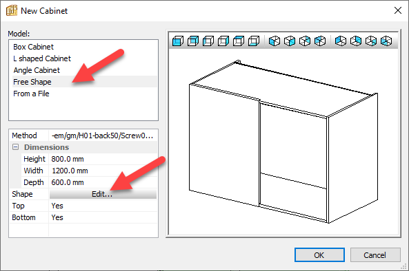
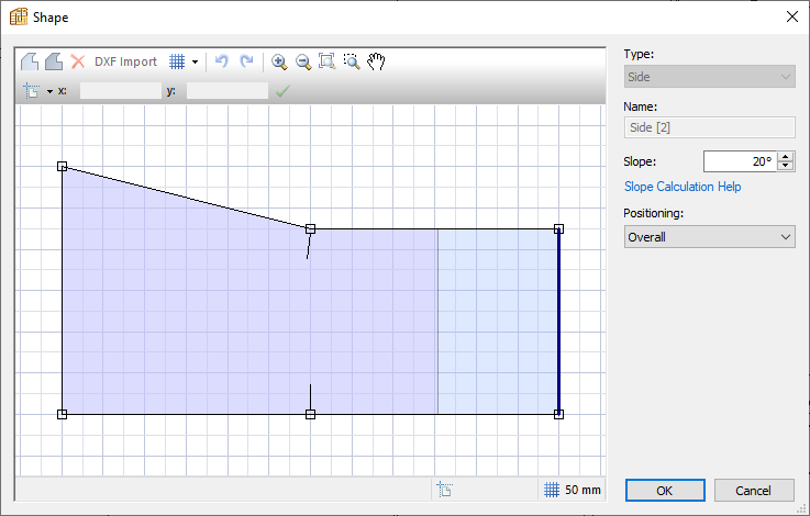
In this Shape editing window, you can drag and add points or use the coordinate system to map out your model, and add slopes.
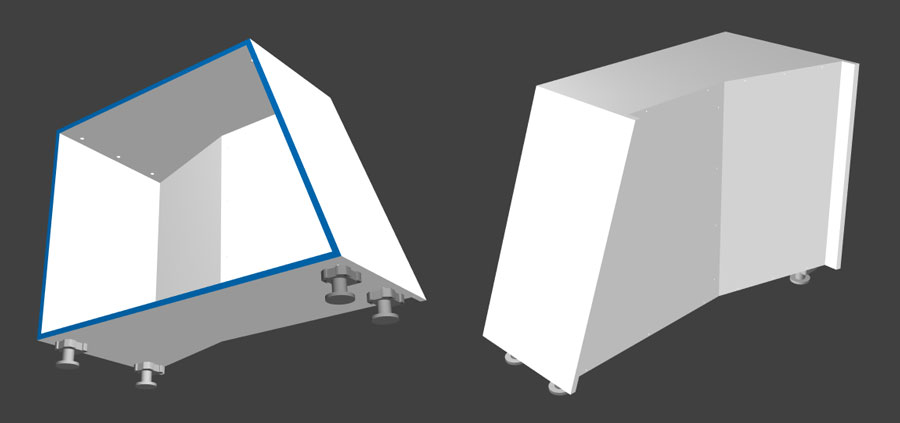
Here’s the cabinet in 3D:
The shape editing tool can also be accessed at any time from the Properties menu.
Sloping top, sloping side and multi slope top
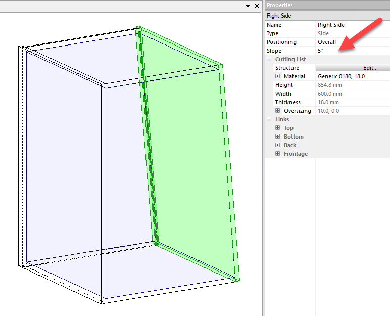
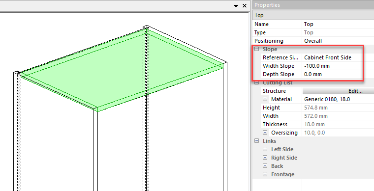
With a part selected, you can easily add a slope in the Properties menu.
You can define the angle of the slope for side panels:
And set dimensions for the slope of the top:
- Width = slope from one side to the other
- Depth = slope from front to back
- Use a negative value to reverse the slope direction
A more advanced Single slope top editing window which includes angle parameters is available via the:
Modify menu > Top
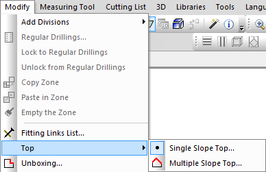
And finally, a very powerful Multi slope top feature allows you to add multiple slopes (in the profile tabs) to the same unit both along the cabinet width and depth, and at any axis in between.
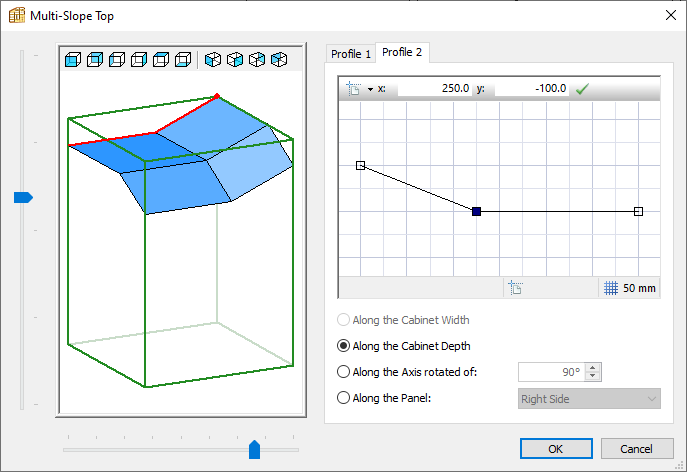
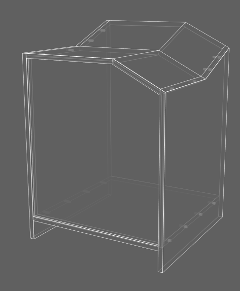
These extremely complex geometries are calculated instantly and all parts with cut angles are immediately available in the manufacturing output.
Free divisions
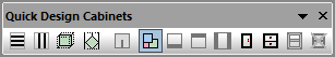
In essence, these are advanced shelves and uprights, and are available from the same location in the Quick Design Cabinets toolbar (highlighted below), with a right-click and from the Modify menu.
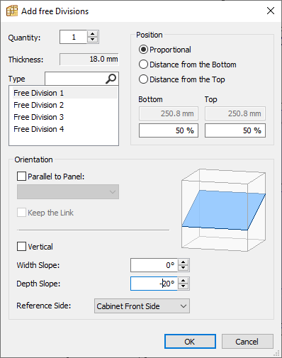
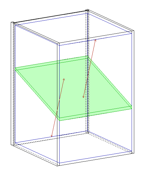
They can be placed at any angle to create anything from a functional shoe rack to a contemporary aesthetic.
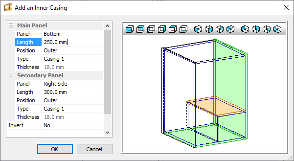
Inner casing
With an inner volume selected, the inner casing feature is available via:
Modify menu > Add divisions > Add an Inner casing
Or the Quick Design Cabinets toolbar:
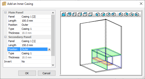
In the Add an inner casing window you define the dimensions and reference panels:
You can then select one of the two new inner volumes that have been created in your cabinet and add another inner casing and so on:
Here is a 2 levels inner casing in the 3D view:
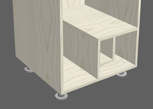
This feature can be used to create highly flexible modern designs.
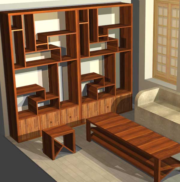
The shelving unit in the contemporary living room model (available in PolyBoard’s Quick Design libraries folder) is a good example of what’s possible:
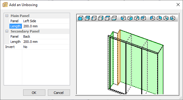
Unboxing
Another useful feature, this time to create a cut out in your cabinet to fit around pipework, wiring or a wooden beam in an attic for example.
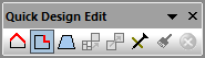
Select an inner volume then click on the Unboxing option in the Quick Design Edit toolbar or via the Modify menu.
All you need to do is decide where to place your cut out, and its dimensions:
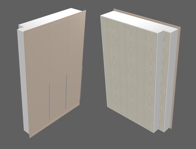
Here’s the 3D of the bedroom wardrobe we’re working on:
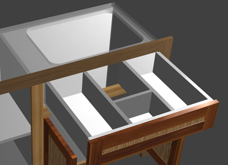
Drawer partitions
With the internal volume of a drawer selected, many standard design components can be added, for example uprights and double backs to create drawer partitions.
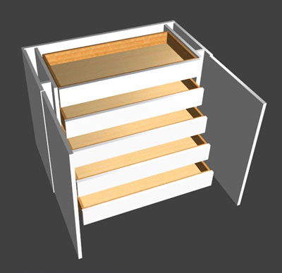
Drawers behind doors
Utilising a combination of these design features offers huge scope in your projects.
Here’s just one example of a simple cabinet incorporating a typical design requirement, setting drawers behind a door with enough space for the required hardware:
There are a few ways to build something like this, we’re not going to go into the details here, but in summary, this was created as follows:
- Adding two uprights and recessing them slightly using the link recess parameter in the Properties menu
- Adding a filler between these uprights and the carcass using double backs
- Adding built-in drawers and setting them back using the Properties menu > Multiple drawers > Slack in-depth parameter
- Select one inner volume then keep left-clicking with your mouse to expand the selection to cover the entire inner volume of the cabinet and add your double door
Panel structures
PolyBoard has a further set of design features specifically for each panel part. It’s possible to split panels into multiple materials, to add curves and other shapes, and also frame and panel assemblies.
To access these commands:
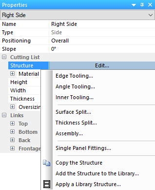
Select a panel > Properties menu > Cutting list > Structure > Edit
More details:
Edge tooling
Apply a shape (or tooling) to the edge of a panel. Shapes are stocked in the Open curves library.
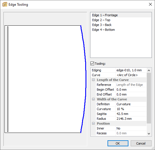
Here we’ve selected:
- Edge tooling to the front of a cabinet side panel (shown in blue)Curve = < Arc of Circle >, one of the shapes in the library
- Optionally you can edit the position and the properties of the curve itself
- Edging has also been applied
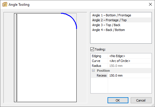
Angle tooling
Apply a shape or tooling to the corner of a panel. Shapes are stocked in the Open curves library.
Inner tooling
Apply a shape or tooling within a panel. Shapes are stocked in the Closed curves library.
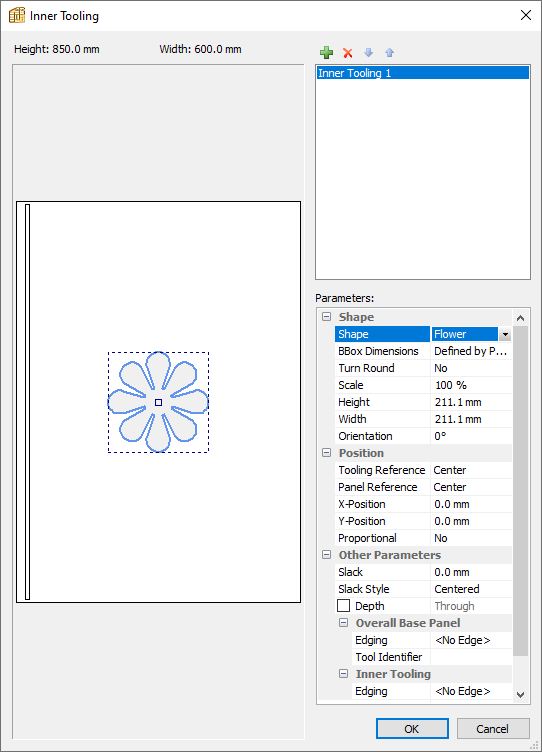
These tooling commands can be used to create a large range of design options.
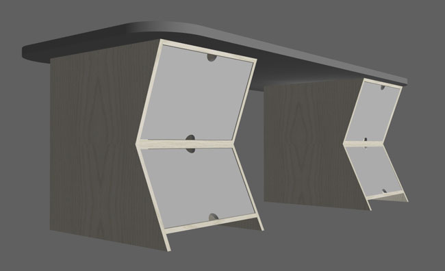
This desk model (included in the Quick Design libraries download) includes angle toolings to create the curved top, and edge toolings for the sloped drawer fronts and drawer handle cut outs.
Surface split
Add more creativity by splitting a panel into multiple materials, shaping the interface between materials with a shape and slack if required. It’s possible to add fittings and edging between each section if required too.
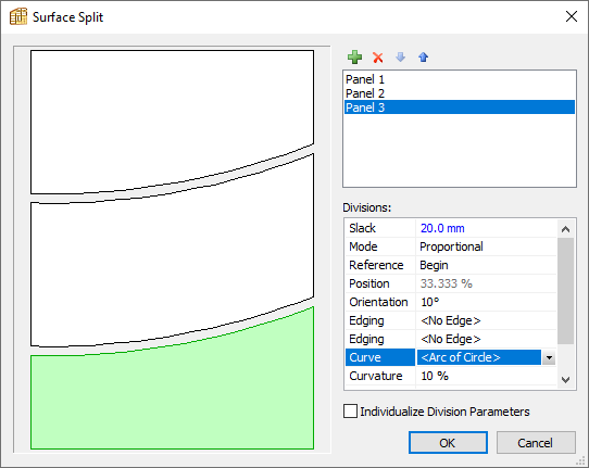
Here we’ve:
- Selected the green + icon to add the 3rd panel
- Added a slack between each panel of 20mm
- Applies a curve to the dividing line between each panel
- Added a 10° angle (orientation) to the curve
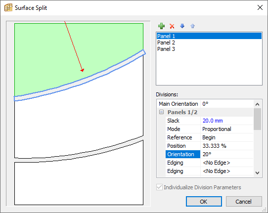
If you select the ‘Individualize division parameters’ check box at the bottom of the window, it’s possible to edit a specific division between the panels. In this case, we’ve increased the angle to 20° for the top division:
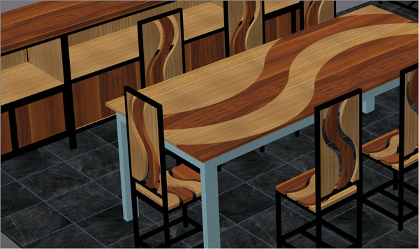
Our metal wood dining room model makes good use of the surface split command:
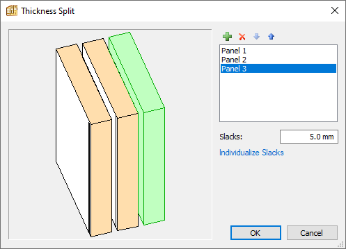
Thickness split
Add multiple materials on top of each other, useful for veneers. It’s also possible to combine this with the tooling features, for example, to create cut outs and reveal the material below.
Assembly
This command allows you to create frame and panel assemblies and comes with a lot of customisation options:
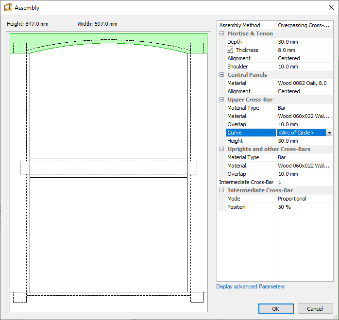
- Set the cross-bars as overpassing, underpassing or mitred
- Edit panel materials, stocked from the Panel materials library
- Edit frame materials, stocked from the Bar materials library
- Apply a shape to the frame
- Adjust mortise and tenon parameters
- Add additional intermediate cross-bars and change their angle from horizontal
- Select ‘Display advanced parameters’ to further fine-tune the construction details
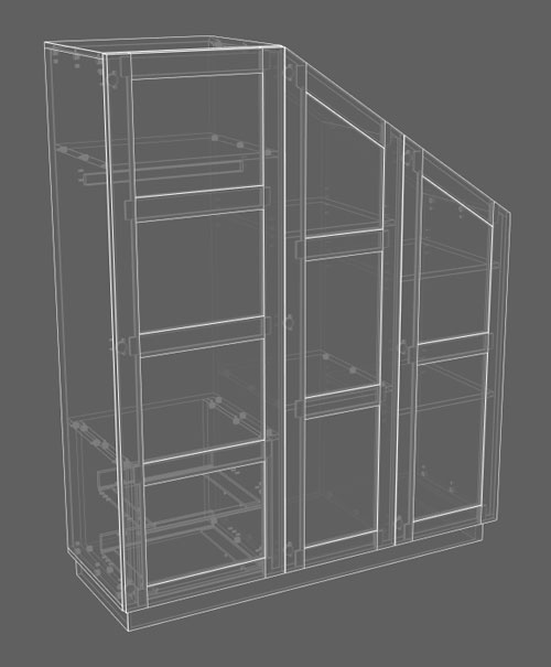
Our sloped wardrobe model, shown below in wireframe, utilises this feature:
Structure management
You can copy and paste a structure from one panel to another.
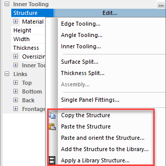
To access these options for some parts like individual doors and drawers, look for the 3 dots… icon:
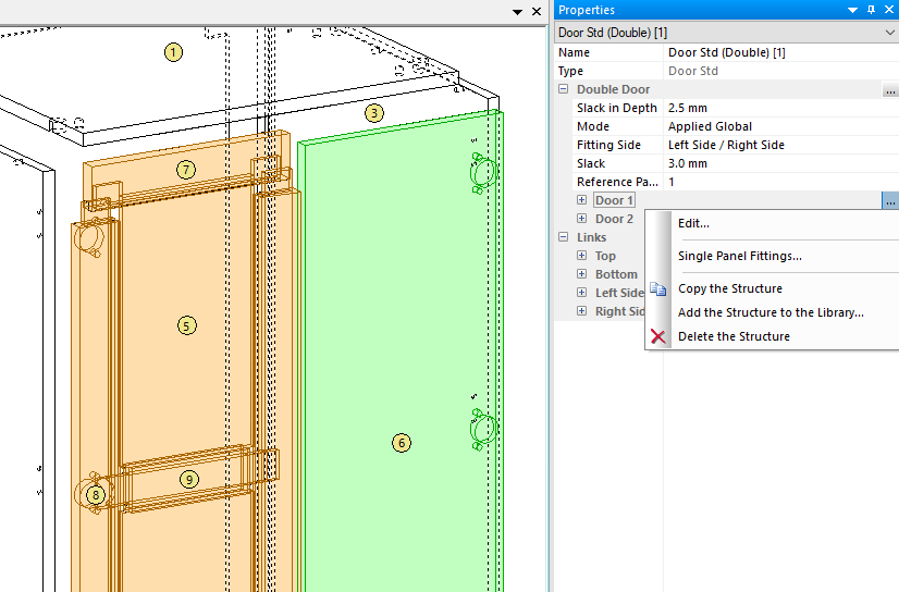
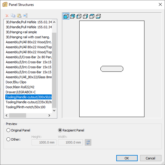
Any structure you’ve created can be saved to the Structures library for easy application.
Select ‘Apply a library structure’ to access it, or select this icon from the Quick Design Cabinets toolbar:
Here’s a simple handle cut out created with inner tooling and saved in the library:
Single panel fittings
Discussed elsewhere, this includes the application of machining and 3D rendering for handles and other accessories to your panel.
More info:
Extended: handles, specialist fittings and other 3D accessories
Joints (links)
In PolyBoard the joint or panel assembly details are defined within the Links section of the Properties menu.
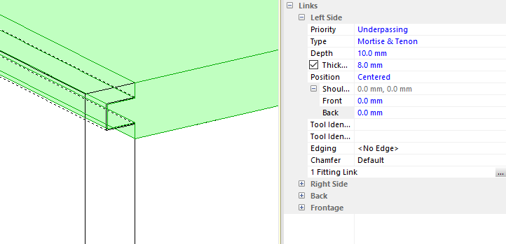
With a part selected, you can then edit the link between it and a neighbouring part.
It’s possible to create a range of joint types including:
- Set priority (which panel overpasses/takes priority and which underpasses)
- Overlapping
- Groove
- Rebate
- Mitre
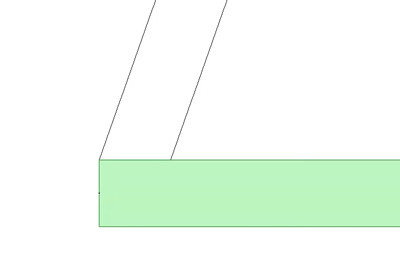
- Mortise and tenon joint/tongue and groove
- Halving
- And add a shoulder to hide the joint
With Links it’s also possible to apply:
- Hardware
- Edging
- Chamfer
More details: