How to set up PolyBoard and OptiNest for import to Maestro
For SCM point to point CNC machines equipped with the CAM software Maestro, PolyBoard can export XXL files that can be read directly with Maestro.
However when using a nesting machine with OptiNest it is necessary to use a DXF file to run the CNC machine.
Maestro can import any DXF file and with a little set up also automatically apply the tool paths so that it’s easy and fast to simply load the OptiNest DXF into Maestro and create the machine file for a SCM CNC without manually applying tool paths.
The DXF set up is done in PolyBoard and automatically transferred to OptiNest. OptiNest will create a new DXF nested file that contains all the parts optimised onto a sheet of material. This can then loaded into Maestro to be automatically tool pathed.
For this to work the DXF file layer names must be set up so that Maestro
can recognise the correct tooling to apply to the DXF geometry.
Let’s see how to do this…
Please note that this guide only contains information for the DXF layer set up, for more information on the other post processor parameters please see our other resources.
Overview
Maestro can import a DXF file and if the layer names are set up correctly Maestro can call and apply a “Technology” to the geometry that is on the layer.
This process requires 2 set up steps :
- That the DXF file layers be named correctly
- That Maestro contains the correct “Technology” file referenced in the DXF layer name
DXF set up
The DXF layer name set up is done in PolyBoard. You can set up the DXF output for each part or for an automatic transfer to OptiNest.
- When using DXF for each part use a DXF post processor
- If exporting to OptiNest use an OptiNest post processor
To do this open a new post processor and in the Post Processor section choose DXF or OptiNest. Maestro needs 2 specific layer types to machine a part. A layer that gives information on the part size and face to machine and layers that define the type of machining to do.
In the DXF part set up, the Panel section draws a rectangle around the part to be machined and it is useful to use this layer to give Maestro the information of the part size and face.
To do this, in the Panel section we must set the layer name to tell Maestro the following:
- That this is a Maestro layer that contains technical machining information
- That we will be working on the uppermost face of the panel
- The thickness of the panel
Here is the code that Maestro is looking for in the layer names.
- The code that indicates a layer contains technical information is XLY
- The code that indicates the working surface is P and the code for the upper face is 1
- The thickness code is H followed by a number that indicates the thickness
Therefore the layer we send to Maestro has to look like this XLYP1H19.
As thicknesses of panels will vary we can put a variable in the layer name that will be replaced by the thickness when PolyBoard exports the DXF file.
This variable is <e>.
You can see and insert the PolyBoard variables by clicking the 3 dots in the Layer line.
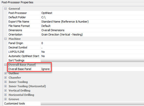
This set up is correct for exporting one part to Maestro but please note that if we are using OptiNest we will need to set the Overall Base Panel export to “Ignore” and the Panel rectangle will not be exported.
In this case the coding of the global dimensions of the part will done in OptiNest for the general limits of the sheet of material set up in the DXF Export dialogue box. Note however,that the naming of the layer will be exactly the same.
To set up a technological layer that will automatically apply a tool path we need to tell Maestro that this is a Maestro layer, what face we are going to machine and what Technology to apply to the DXF entities on the layer.
- To tell Maestro that the layer is a technological layer we use the same code XLY
- The face to machine is indicated by the code P and 1 indicates the upper face
- To tell Maestro to apply a Technology we must use the code T followed by the name of the Technology between 2 “$” signs i.e. $TECHNOLOGY1$, the name of the technology must be the same as that set up within Maestro
To setup the cutting of the outline of the parts
In the Outline > Layer section we can type XLYP1T$OUTLINE$ (we will have to set up the Maestro Technology called “OUTLINE” before importing the DXF file).
To setup vertical drilling
Using the same principles as in the Outline layer set up, in the Vertical Drilling section type: XLYP1T$VDRILL<p>$
In this example VDRILL<p> is the name of the Technology that Maestro has to apply.
The variable <p> (which can also be inserted using the 3 dotted button) will be replaced with the drilling depth when PolyBoard exports the DXF file i.e. for a hole 12mm deep the DXF file will contain a layer named XLYP1T$VDRILL12$.
Note here that Maestro must have a Technology called VDRILL12. Note also that although we are setting a depth in PolyBoard the real machined depth will be defined by the applied Maestro Technology and not the PolyBoard layer name.
To setup Grooves
Set the layer name to XLYP1T<p>$GROOVE$
To setup Inner tooling
Set the layer name to XLYP1T$INNERTOOL<p>$
To setup Edge tooling
Set the layer name to XLYP1T$EDGE$
Setting up OptiNest
As stated before if using the PolyBoard to OptiNest export, as we will be nesting the shape of the parts, it’s important to export the Outline and not export the Panel.
In this case it’s important in the DXF section of the PolyBoard OptiNest post processor to set the option “Overall Base Panel” to “Ignore”. This stops PolyBoard drawing the Panel shape in the exported DXF file.
The layer coded for the part size is now removed from the individual parts and can now be set in OptiNest.
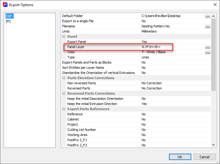
To do this, in OptiNest go to Files > Export Options. Select the DXF section. In the Panel section set the Export Panel to “YES” and in the Panel Layer, type in the code that we previously set up for the Panel layer in PolyBoard i.e. XLYP119 or XLYP1H<e>. In OptiNest the variable for thickness is <th> instead of <e>. So you need to enter XLYP1H<th>.
Setting up Maestro Technologies
Maestro Technologies are machining styles that can be saved in a file and applied to new geometry. These Technologies differ from the machining in that they do not have an associated geometry.
As the technological information is often much more than the geometrical information it is useful to save them in order to apply them to other geometries. To create a Technology do a project with a single machining and save it as a Technology.
Use the Save as technology command to create the Technology file.
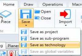
You will be asked to save the Technology file with the .tchx extension.
To reuse these files they must be located in the “Technologies” sub-folder of the Maestro installation folder. More information on creating Technology files can be found in the Maestro manual.
You must create as many Technology files as you have machine operations in the DXF files and their names must match the text between the $ signs in the DXF layer names.
Note that as PolyBoard will be replacing the variables <e> and <p> with a number, it’s important to have the Technology file with the number and not the variable.
For example, holes drilled at 12mm deep will be drawn on the WLYP1T$DRILL12$ layer in the DXF file.
To load a DXF into Maestro use the Import DXF command:
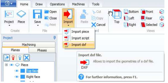
If Maestro finds the correct Technology .tchx files that correspond to the text between the $ signs in the layer names the appropriate machining will be applied to the DXF geometry found on that layer.
Note that for drilling Maestro will automatically find the correct tool according to the diameter of the hole drawn by PolyBoard.
Special case: working in inches
In both PolyBoard and OptiNest it’s possible to set the working units to inches. In OptiNest you have 3 types of units:
- Working units that your interface is set to
- Import units are the units of the DXF files you load into OptiNest and export units
- Units of the DXF files you export from OptiNest to your CAM programs
If your working units are in inches it’s important to know how PolyBoard, OptiNest and Maestro import and export files and set the correct import and export units accordingly.
When using inches as a working unit in PolyBoard please beware that the OptiNest post processor exports DXF files which are automatically converted to millimetres.
This means that to import the files correctly into OptiNest, even if your OptiNest working units are set to inches, you must set the OptiNest DXF import option to millimetres.
OptiNest working units are set in Tools > Units:
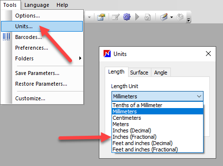
Setting the working units to inches will enable you to set your stock sizes in inches.
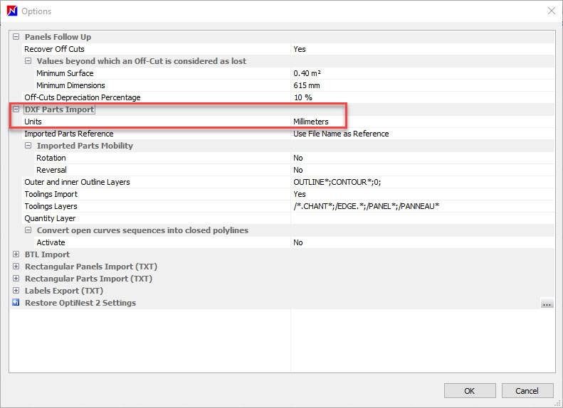
To set the OptiNest import units, go to Tools > Options > DXF parts import:
To use OptiNest’s DXF nesting maps you must set the OptiNest export option to the units that your CAM software (in this case Maestro) is set to import.
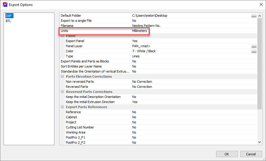
To set the export units go to File > Export options > DXF:
Be careful to check your Maestro import configuration before setting the OptiNest export units.
More information
For more information on using Maestro please consult the Maestro manual.
We also have an overview of the integration of PolyBoard with SCM CNCs.
And don’t hesitate to contact us if you need help setting up PolyBoard or OptiNest for use with your SCM machine.