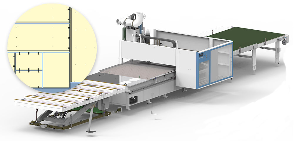
OptiNest integration with your CNC machine
As long as the CAM software that comes with your CNC accepts DXF files, it will be able to accept OptiNest’s nesting results. The CAM software will then convert this information into the machine code to run your router.
OptiNest outputs layered DXF files which can include:
- The panel geometry
- The nesting pattern for each panel which shows how the parts are placed
- All machining details associated with the parts, including the outline to cut the part out, and the toolings required for hinges, drawer sliders, panel fittings etc
These files can be loaded into your CAM/CNC software to run your machine.
If you’re working with PolyBoard, the part and tooling layer names are set in PolyBoard’s OptiNest post processor to match those required by your CAM/CNC software.
The same layer names will be included in OptiNest’s output. The CAM/CNC software will recognise them and apply the correct tooling automatically. The layer name can be coded if required by the CAM software e.g. for Masterwood CNCs.
Alternatively, the DXF or csv part import will define these layer names. Note, the csv import is more limited as layers cannot be defined.
As an example, we have more information in the link below on how OptiNest will output to VCarve Pro, a CAM software for nesting CNCs:
VCarve Integration with PolyBoard and StairDesigner
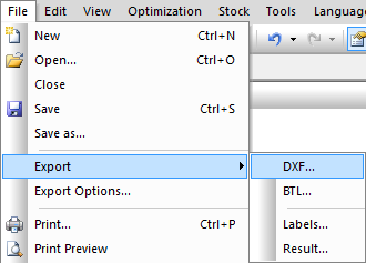
To perform the DXF export, go to File > DXF.
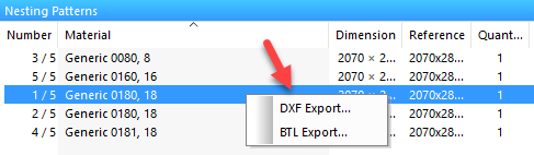
It’s also possible to run the DXF export for a single nesting pattern, right click with the mouse on the appropriate nesting pattern from the list at the bottom of the optimization results window.
OptiNest’s DXF export parameters
To view and edit the DXF export settings, go to File > Export options.
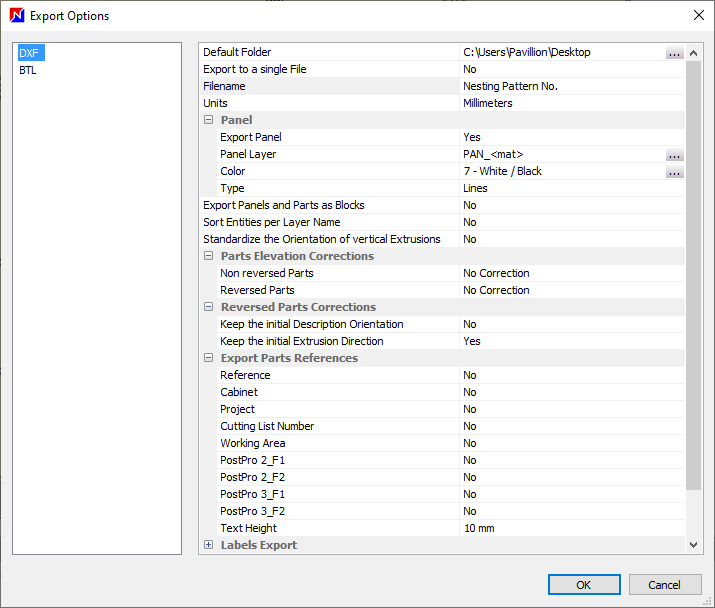
General settings
- Default folder: choose folder location for file output
- Export to a single file: all the elements of the same nesting plan will be placed in the same DXF layer; not suitable for cabinetry
- Filename: name of the DXF file followed by the number of the pattern
- Units
Panel
- Export panel: this may or may not be required for your CNC machine
- Panel layer: this layer name is not generated by PolyBoard or any other import, it is set here in OptiNest if required
- Colour: set the panel layer colour if required
- Type: lines or polyline
Next three parameters
- Export panels and parts as blocks: exports the part description once only and describes each nested part by a translation and rotation; useful in cases of very large quantities of files
- Sort entities per layer name: parts are exported layer by layer; of limited use in cabinetry
- Standardise the orientation of vertical extrusions: corrects the direction of extrusions, applicable to some very old CAD software
Correction parameters
- Parts elevation corrections: aligns parts and associated toolings to a specific vertical level
- Reversed parts: option to allow inversion of parts and the direction of extrusion
Combined, these parameters allow compatibility with CNCs that do not employ a 3D coordinate system.
Export parts references
Select whether to include these additional references within the DXF file.
For more information, go to:
Essentials: parts import (additional references section)
Labels export
If activated this will output labels as bitmap files and as G-code. This output can be used by machining centres to automatically print and place labels.
The bitmap file provides the label image, the G-code element confirms the correct location of the label on the panel.
OptiNest offers an ANC and Biesse configuration.
Here is the ANC set up.
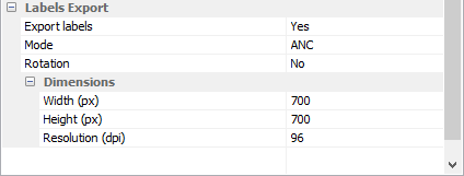
It includes the following parameters:
- Mode: ANC or Biesse
- Rotation: used for automatic labelling installations; rotates the bitmap file according to the panel rotation; during printing the angle of rotation of the part in situ in relation to its reference orientation is output; in some cases, the label is automatically rotated by 90° for the tool that is going to apply it
- Dimensions: of the bitmap image
Sample OptiNest output
You can download our trial version of OptiNest but you won’t be able to see full details of the optimisation, only the nesting map. Below you can download a complete optimisation.
Sample nesting optimisation files
The download include a nesting map and report, plus DXF files to load into your CAM software for testing. You won’t be able to run your machine until you have configured your CAM software to add the tool paths and specifications for your CNC.
Test OptiNest with your CNC machine
Please contact us if you would like to discuss how to include OptiNest in your manufacturing process. We can look at the best option for you and test it on your CNC machine.
Contact us to test OptiNest with your CNC machine
More advice on setting up OptiNest with your CNC
For additional guidance on some specific production configurations, click below for details: