Parts import
Once the stock is set up, it’s time to add the parts ready for optimization.
PolyBoard import
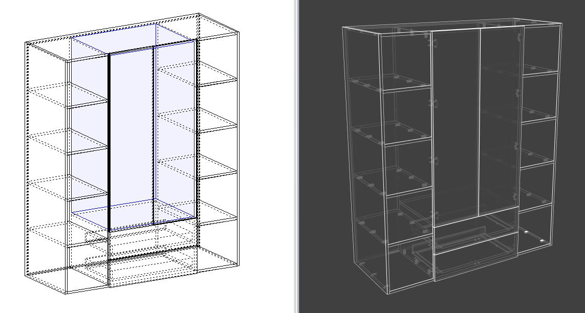
PolyBoard Pro PP integrates seamlessly with OptiNest.
Once your design is complete in PolyBoard, all part information including machining details is sent to OptiNest as layered DXF files.
Go to File > Post processor export > select the appropriate OptiNest post processor.
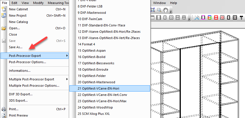
A range of OptiNest post processors are already set up in PolyBoard. Here we’ve chosen the post processor for VCarve CAM software and horizontal CNC machines.
All post processors can be modified, or you can set up a new one as required. We offer post processor set up packs if you would like help with this.
PolyBoard’s OptiNest post processors are essentially the same as a standard DXF post processor. More information on the post processor set up can therefore be found here:
PolyBoard CNC integration: DXF post processor parameters
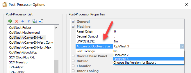
There is one extra parameter in a PolyBoard OptiNest post processor however, this is a line to trigger OptiNest to automatically open with the DXF already imported.
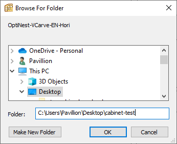
Select a location to save the resulting files and select OK.
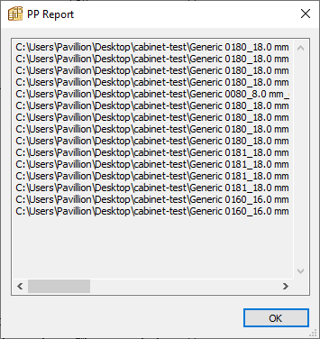
PolyBoard generates a post processor report confirming the details of the part by part DXF files that have been created.
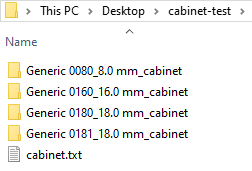
These DXF files for each part are stored in sub-folders organised by material.
Here is a list of DXF files for a single material within one of those sub-folders.
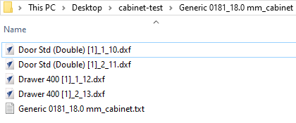
A text file is also created with parts data which may be required by your specific CAM software.
Assuming you’ve chosen this option, OptiNest opens automatically with all parts available. Alternatively, open OptiNest manually, select multiple DXF files and import.
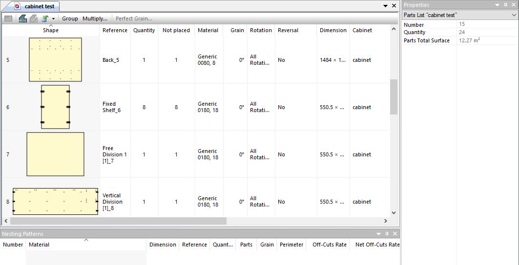
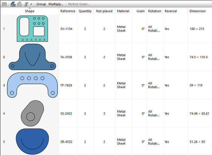
The Properties menu on the right summarises the parts list.
PolyBoard includes detailed information on each part which is transferred to OptiNest. Click on an individual part to view the details, these are also now displayed in the Properties menu.
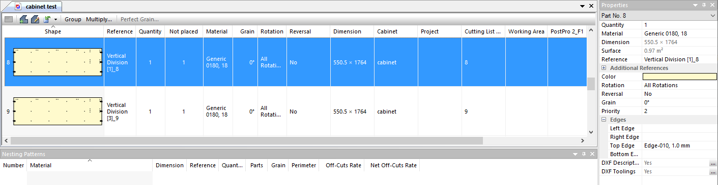
Data fields include:
- Reference: annotation to identify the part
- Quantity: total number of identical parts
- Not placed: quantity of parts that haven’t been nested
- Dimensions
- Material
- Grain direction
- Rotation: rotation options are allowed during nesting
- Reversal: whether the part can be reversed during nesting
- Cabinet name: PolyBoard’s cabinet file name
- Project name: PolyBoard’s project file name
- Cutting list number: a reference from PolyBoard’s cutting list
- Priority
- Edging position and material
- Additional references to add to your labels or OptiNest file output
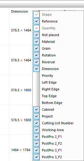
To select data fields for display, right click on any column title area and select which fields are visible from the drop-down menu.
With a part selected, the Properties menu allows you to view and edit data, including the material, quantity, and rotation and reversal preferences.
Some additional information is also present including:
- Surface area
- Colour: on screen and visible in the nesting pattern printed output
- DXF description
- DXF toolings
Grain direction
If a part includes a grain direction, OptiNest will nest the part so that the grain lines up with the panel’s grain.
The grain is assumed to run along the longest dimension of the panel unless you rotate the grain direction angle in OptiNest.
An additional perfect grain feature is available:
Extended: perfect grain management
Additional references
Extra text fields can be added to the parameters of each part. They can be added manually, imported as part of a csv file or imported directly from data fields built into PolyBoard.
These can then be added to your labels.
These references are set up in Tools > Preferences.
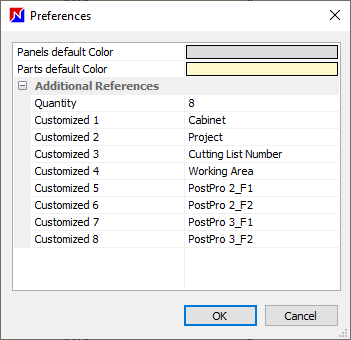
Select the quantity and type the reference names.
If the data fields are in PolyBoard, or in your csv import, they will be added automatically to the part parameters in OptiNest.
Priority
The priority can be set in OptiNest.
If importing with PolyBoard, the following part priorities are automatically allocated:
- 1 = parts with toolings on a single face
- 2 = parts with toolings on both faces
The priority is referenced within the optimization parameters to adjust whether parts with different priorities are placed on the same nesting pattern.
More details:
Optimization parameters (Advanced tab)
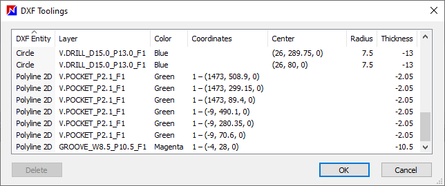
DXF description and DXF toolings
Click on the 3 dots icon next to these parameters in the Properties menu to view details.
The DXF description shows the outline and inner outline layer name.
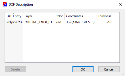
DXF toolings lists all other layers in the DXF file, and parameters relating to the geometry of each. Each layer relates to a specific tooling operation.
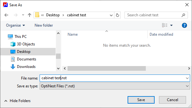
Saving your progress
A .nst OptiNest file can be created that includes the part information. After an optimization has been run, the nesting results will also be saved in the same file.
Go to File > Save as and select a destination folder.
This file can be opened at any time to access the nesting project data.
Alternative software integration
OptiNest can be started from other software packages using a Windows command line. This will import the parts to OptiNest and export the results file following optimization.
Please contact us for details.
DXF file import
Parts for a panel cutting list can be imported as DXF files.
When OptiNest is first opened, select New document to open an empty project window.
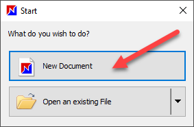
Alternatively, go to File > New or select the New icon:
Then go to Parts import > Parts DXF import (also available via the Edit menu):
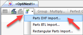
Browse to and select one or more DXF files for import. The parts list will be populated as described in the PolyBoard import section.
Some of the parameters that are provided by PolyBoard are not included in this import. For example, there is no data field to confirm the quantity of each part. Instead, a DXF file for each identical part would need to be imported.
Alternatively, this and other fields can be added in OptiNest.
Here’s an example import of complex metal components:
Go to Tools > Options > DXF parts import to set up the import parameters.
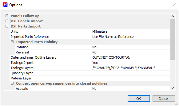
Options include:
- Units
- Imported parts reference: how to define the reference field in OptiNest
- Imported parts mobility: whether they can be rotated and reversed
- Outer and inner outline layers: define which layer name/s represent the part outline and inner outline
- Toolings import: whether to import toolings or not
- Toolings layers: define specifically which layer names are toolings and/or which should be excluded; any layer that is not defined as an outline will be assumed to be a tooling, unless excluded
- Quantity layer: whether a specific layer should define the part quantity
- Material layer: import the material name in a configurable DXF layer
- Convert open curves sequences into closed polylines: sometimes your part geometry may not be completely closed; create closed polylines where necessary to facilitate import
If using PolyBoard with OptiNest, installation of PolyBoard’s Quick Design libraries will preload a typical configuration of these options into OptiNest.
Hover over the toolings layer for advice on how to manage the selection criteria.
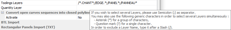
For example:
- ; allows the selection of multiple layers
- * replaces a group of characters, so P* would select all layers starting with a P
- ? replaces a single character
- / used at the beginning of a layer name excludes it
In the image above, edge and panel toolings are excluded, as they are typically irrelevant for nesting.
If you import a single DXF file, an additional information window will appear.
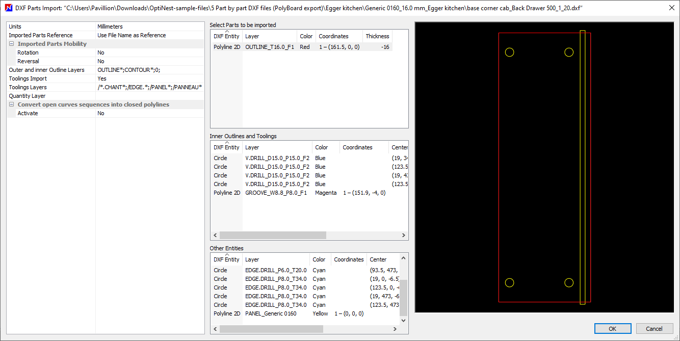
The section on the left confirms the import settings from the Options menu.
The central three windows show, from top to bottom the following layers:
- Part outline details
- Inner outline and other toolings
- Excluded toolings that will not be imported to OptiNest
Click on any line to highlight the tooling in the image window on the right. Click on an empty space in the central three windows to deselect all of those layers.
These windows allow you to cross reference how the import options are applied to specific parts to confirm the set up is correct.
Click OK to import the part to OptiNest, or cancel and instead import all required parts.
CSV import
Part information can be defined in a csv file.
Go to the Parts import menu > Rectangular parts import and select a csv file to import.
Go to Tools > Options > Rectangular part import (TXT) to set up the import and to ensure the fields in the csv file map to the correct data fields in OptiNest:
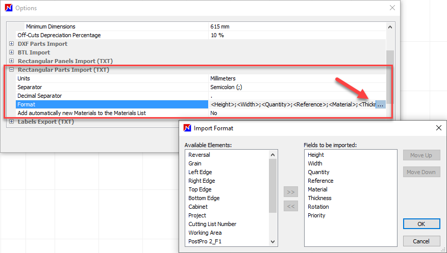
The separator for example a semicolon (;) must also match.
As discussed previously, drag field names into place or select a data field and use the arrows to move it between the two windows. Use the up and down buttons to define the field order.
★ Tip ★
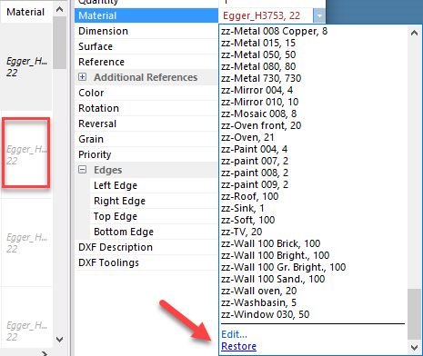
If a material is imported that hasn’t yet been set up in OptiNest, it will show as greyed out.
To quickly add this material:
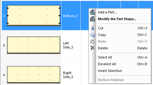
Right click on the part > Restore material.
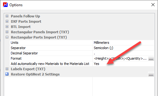
The import preferences include a setting to automatically add a material that hasn’t yet been defined. Note, the stock of the material must still be created before optimization.
Manual creation in OptiNest
A final option is to manually create parts in OptiNest. Click on the Add a part button > select the part shape.
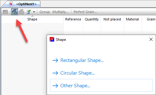
The options are the same as those for manual stock set up:
- Rectangular shape
- Circular shape
- Other shape
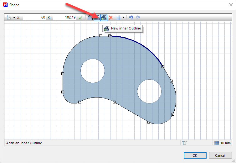
The Other shape option allows you to draw a part using the Shape editing window. X and Y coordinate boxes are available to draw to exact dimensions.
Note that there is an inner outline option available, and it’s also possible to apply curves by dragging a line rather than a point:
Additional part list management buttons
Right click with the mouse on a part to access a menu of common options.
Alternatively, double click on a part to open the Shape edit window.
Group and multiply
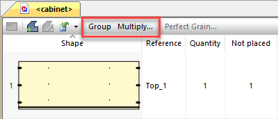
The Group option groups strictly identical parts together on the nesting patterns. Additional references must be identical too.
With the Multiple option, select a part and multiply its appearance in the part list by a specific factor:
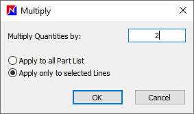
Or check ‘Apply to all part list’ to multiply all parts in the list by this factor.
★ Tip ★
- Use the shift key to select adjacent sets of parts
- Hold down the control key to select multiple lines
- Select CTR + A to select all parts