DXF post processor parameters
PolyBoard has an extensive range of post processors that can be flexibly configured to work with practically any CNC machine. This includes both well-known branded machines with their own specific file formats (native files are output from PolyBoard) and direct G-code machines using an external CAM software that require DXF files.
If you are utilizing one of our native file format post processors, normally the CNC software will read the file and apply the correct tool and toolpath for immediate manufacturing. Many of the settings in PolyBoard are available but not required. Depending on the CNC software, a coded layer DXF input is also possible.
Direct G-code machines require DXF files of each part that are read by an external CAM software. The operator can apply the required toolpath configuration and tools. After this, the files are processed in the CAM software to generate the G-code that runs the machine. With PolyBoard’s ability to name the layers within the DXF file, this process can be automated e.g. by creating a toolpath template based on layer recognition using VCarve CAM software.
We focus here on the DXF post processor.
Click below for more information on:
- CNC machine integration with PolyBoard including good introductory video
- CAM software integration
- All CNC integration articles
Please note: we offer a post processor set up service if you need help integrating our software with your machine.
Below we describe the parameters of the DXF post processor. Many of the general parameters will apply to the native file post processors too.
General parameters
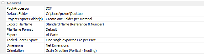
General
Post processor
Select the type of post processor (DXF or OptiNest).
The OptiNest type is used in conjunction with our optimisation software OptiNest.
Default Folder
Select a destination folder for the output files from the post processor.
A specific folder can be chosen relating to your file organization.
Project Export Folder(s)
Define the folder export type requested.
- All files in one folder (point-to-point manufacturing + no sorting)
- One folder per cabinet (point-to-point manufacturing + part sorting per cabinet)
- One folder per material (Nesting manufacturing + sorting per material type)
This setting also depends on the applied manufacturing organization and machines.
Export File Name
Type of file name outputted.
- Standard Name (Reference & Number), e.g. Top_1_f1.dxf
- Number Only (follows the cutting list number), e.g. 1_f1.dxf
This option also refers to the options in the Tools > Preferences > Parts references menu.
File Format
Written format type of the file.
- Default
- Without Accents and without special Characters
Depends on the CNC software and the ability to manage special characters.
Export
Type of export.
All parts can be exported, or only parts that contain tooling operations. Depends on the CNC setup.
- All parts (nesting or point-to-point with oversize for profiling)
- Tooled Parts (point-to-point or vertical CNC)
Tool Faces Export
Type of face export.
Allows you to export one file per face OR one file per part.
- One single exported File per Part (6-sided vertical CNC or nesting CNC)
- One exported File per Face (5-sided vertical CNC or point-to-point)
Dimensions
Output Dimensions.
- Overall dimensions (with pre-mill edgebander)
- Net dimensions (no pre-mill edgebander)
Orientation
Output orientation of the parts according to the machine requirements or constraints
In conventional mode, the front edges of the cabinet would face to the right (or left).
In parts rotation mode, the front edges will face forward or backwards.
Additional reversal options are available! Example: with invert rotation of all the parts in rotation mode, the back edge is passed to the front of the machine.
- Conventional
- Parts rotation
- Grain direction (horizontal)
- Grain Direction (vertical)
- Grain Direction (vertical Nesting)
- Horizontal max dimension
Available options depending on the type of rotation (used for machine constraints):
- Height max
- Width max
- Invert rotation (all parts and/or doors)
Machine
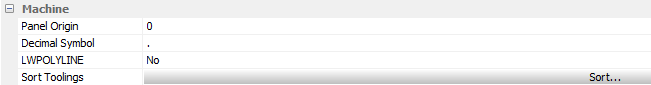
Panel Origin
Defines the origin as the panel’s top on Z0 (0) or the bottom (Thickness).
Decimal Symbol
Standard set on point.
By layer coding, another decimal separator might be needed depending on the software, e.g. Masterwood requires P as a decimal separator.
Sort Toolings
Indicates the order in which the tooling is applied to the parts.
For example, first, all the drilling operations and lastly, the profiling.
Overall base panel
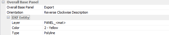
Can be ignored or exported in the DXF file. This depends on the application using the DXF. Some software requires this panel to define the part size.
If exported, other parameters such as orientation, layer names (+ variables), colour and line type can be defined according to the required output format.
DXF entity contains the layer name that can be given with additional variables if needed.
Machine operations
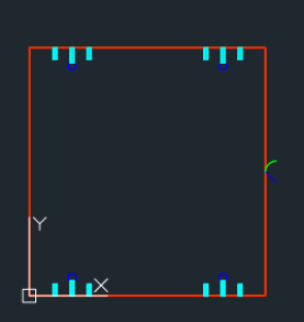
Outline
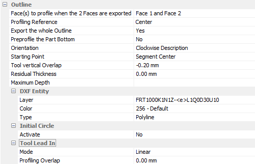
General parameters to control the outline cut (profiling) of the parts.
The following parameters are explained further below:
Profiling reference
Positioning the oversize on the panel to be profiled.
Export the whole outline
Full or partial outline export.
Orientation
Drawing direction of the vector.
Starting point
Position of the start of profiling in the centre or a corner of the part.
Tool vertical overlap
Tool protrusion beyond the panel.
Residual thickness
Creates a pre-cut with the profiling tool (other pass(es)) and therefore leaves a thickness for the final cut.
Activate if this value is greater than 0 mm; mainly useful for cutting on bleeding boards or the use of two reverse cutting tools for cutting melamine.
Tool Lead in
Lead-in mode for the circular tool.
Radial in green or straight > Linear in blue.
Profiling overlap
Distance from the part of the lead-in.
Chamfer
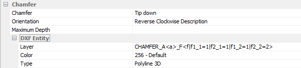
Default tool management for machining mitre cuts.
Three possible options:
- Tip down: tip (longest part) longest forced downwards
- Indifferent: the position of the part will be determined by other related parameters
- Ignore: to cut the workpiece at a right angle; chamfer is not exported
Inner Tooling
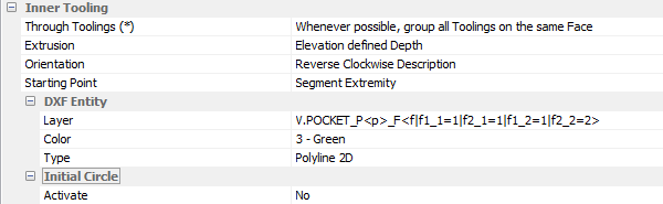
Default tool management for inner tooling.
Through Toolings
Either grouped to avoid flipping or respected for tool constraints, for example with a tool that only works in downward cutting.
Inner Tooling (Horizontal)
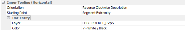
Default management of horizontal inner tooling application.
Vertical Drilling
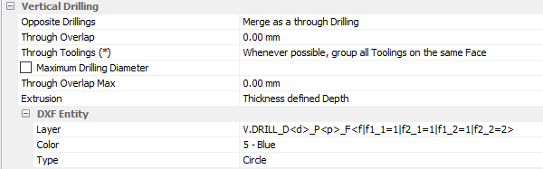
- Opposite drillings: group opposite drillings or keep the drillings on each face
- Through overlap: the value of the drilling depth beyond the panel
- Maximum drilling diameter: the diameter from which drilling is converted to an inner tooling
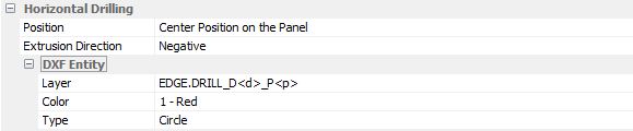
Horizontal Drilling
Groove
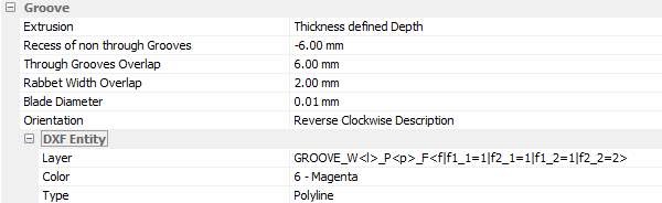
- Recess of non-through grooves: allows extension of non-through grooves for assembly purposes
- Through grooves overlap: allows groove extension for a full squaring of the panel groove
- Rabbet width overlap: adjustment of segment width to take account of offsets such as tool diameter
Customized Tools
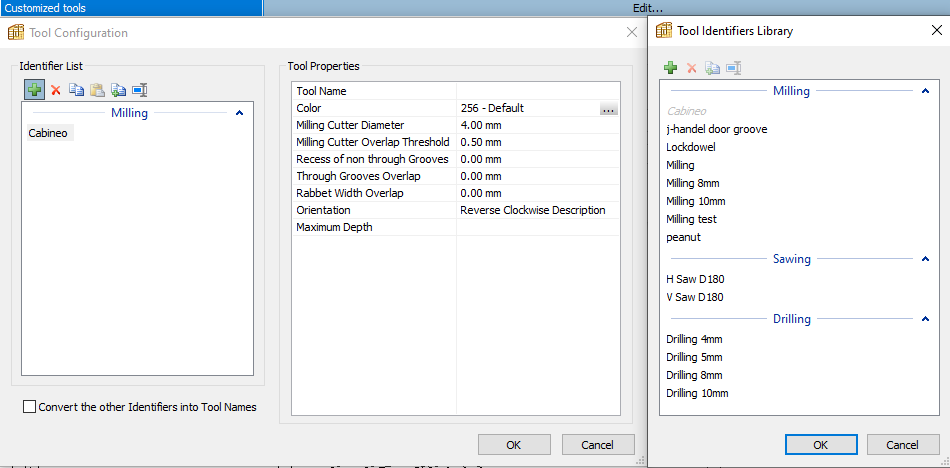
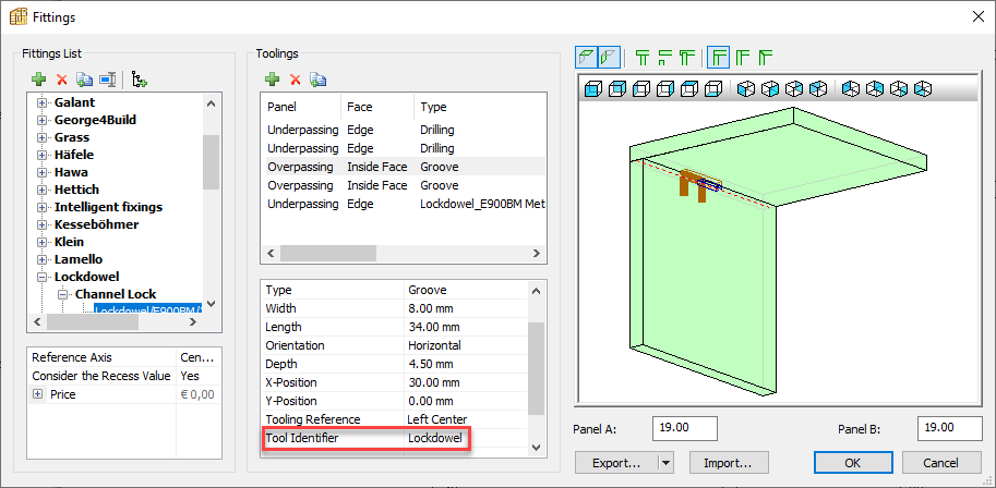
Allows specific tools to be selected depending on the type of application by using the Tool identifier option in PolyBoard.
By using the Tool name variable in the DXF entity, the tool name for a specific operation can be added to the layer name.
PP report file
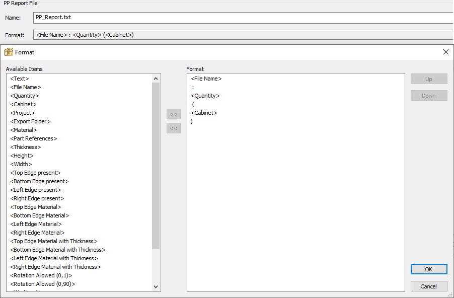
This file is generated at the post processor output stage and can be used in various CNC softwares to generate specific machining operations if required.