Optimization parameters
Once the stock is set up and the parts list has been populated, we’re ready to run the optimization.
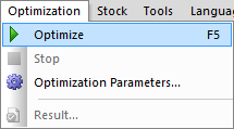
Click on the Optimize icon, or select F5 on the keyboard:
Or go to the Optimization menu > Optimize:
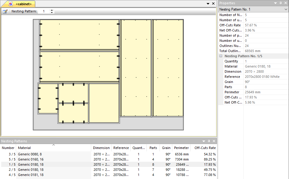
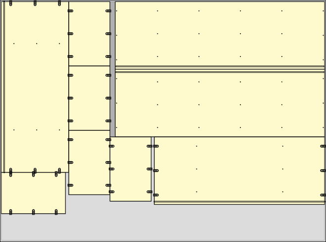
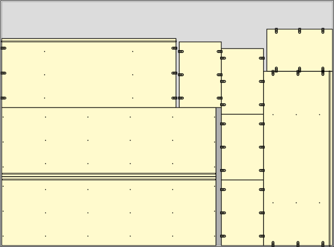
The optimization runs for a short period of time and the results are shown on screen:
Please refer to these resources for details:
Optimization results and labels
The way OptiNest optimizes parts for nesting can be adjusted in the software’s optimization parameters.
The flexibility offered allows you to run effective optimizations for small to medium workshops, or fine tune large scale industrial manufacturing where every second or fraction of a % of material saving counts.
Adjustments can be made to balance optimization speed, cutting speed, material waste and other production preferences.
Optimization for cabinetry deals predominantly with simple shapes, typically the time taken to calculate the nesting patterns is very quick. On the other hand complex shapes will take longer to place, we’ll see that some of the parameters are more useful in this latter case.
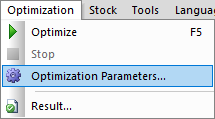
To view and modify these parameters, click on the Optimization parameters icon:
Or go to Optimization > Optimization parameters:
General parameters
The first tab of the Optimization parameters window shows the general parameters:
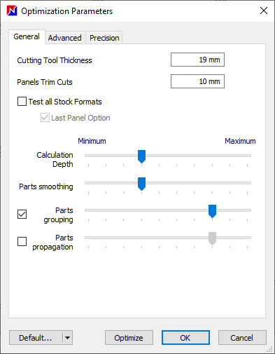
Note also that an Optimize button is included at the bottom of the window. This makes it easy to adjust parameters and run multiple simulations to see which result in the best outcomes for you.
Cutting tool thickness
This equates to the thickness of the cutting slot. This is the minimum distance between parts on the nesting pattern.
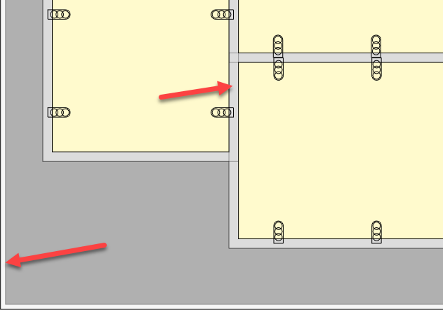
Panels trim cuts
Add a trim cut if panel stock is rough cut. The boundary of the nesting pattern boundary will sit inside the panel edge by this distance.
The image shows the trim cut around the panel, and also a gap between each part which is the cutting tool thickness.
Test all stock formats
Whether to test all panel formats and compare the results. Otherwise the first available panel format will be used.
The last panel option prioritises a panel format that allows the placement of all the remaining parts on a single panel, reducing material usage.
Calculation depth
The first of four sliders that all adjust the optimization algorithm.
Calculation depth gives an indication of how many part positions will be tested before moving on to the next part.
Cursor position 1 (far left) is the fastest vs position 10 (far right) which results in the best material savings.
Parts smoothing
To run the optimization efficiently, OptiNest creates an approximation of each curved part made up of straight polylines.
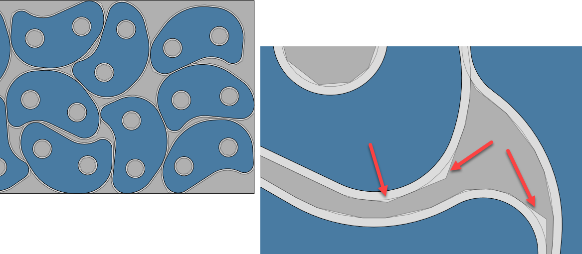
The greater the number of polylines used, the smoother the curve and the more efficient the nesting.
Cursor position 1 offers no smoothing and a less efficient placement of curved parts, but is the fastest.
Position 10 offers the greatest smoothing, is more efficient but is slower.
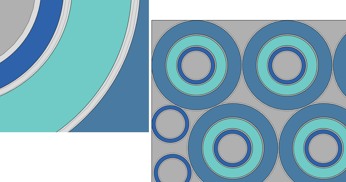
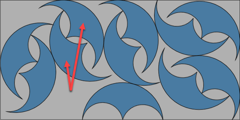
This image shows ring-shaped parts nested inside each other using a high smoothing parameter.
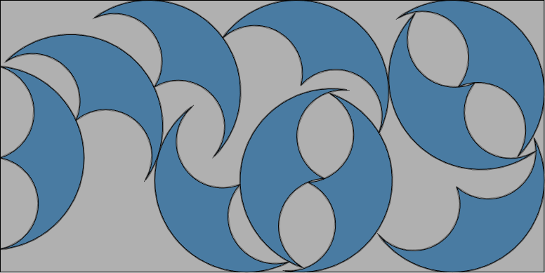
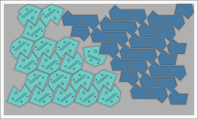
Parts grouping
Two similar parts with complementary shapes will be placed together. This will form a virtual part which is then nested; this may increase the efficiency of the optimization.
Parts propagation
Propagation is a useful placing method to nest a small variety of part shapes but large quantities of them. It helps to minimise the off-cut rate.
As a general rule, the identical parts are grouped together, then that grouping is replicated. Bigger panels will result in an improved optimization.
Save optimization settings
At the bottom of the parameters window it’s possible to select from a set of pre-configured optimization parameters.
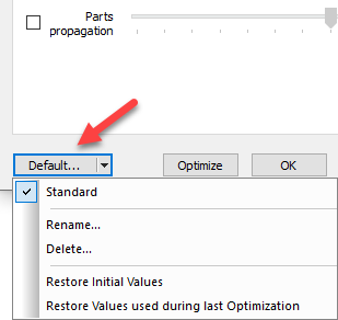
If you are using OptiNest and PolyBoard together, when you install PolyBoard’s Quick Design libraries a set of optimization parameters is automatically added to OptiNest.
This default configuration is called Standard.
If you make changes to the parameters, you will see a new Save option to save them for future use.
Advanced parameters
An additional Advanced parameters tab is available:
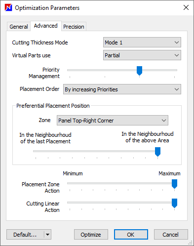
Cutting thickness mode
This governs how OptiNest handles the cutting tool thickness parameter defined on the General tab.
- Mode 1: performs a virtual enlargement of parts and the panel by half the cutting tool thickness and assumes there is no additional cutting loss, recommended for simple shapes
- Mode 2: uses real part dimensions, should lead to slightly less off-cuts, test impact for more complex shapes
Virtual parts use
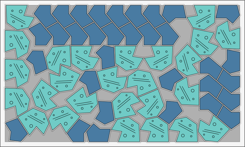
Relevant to non-rectangular parts, OptiNest generates from any part three virtual part shapes that can be used for the optimization, the actual part sits inside each:
- A rectangular bounding box
- A convex envelope
- A polygon based on a low level of smoothing
The different options define which approximation is chosen:
- None: the polyline shape is used for nesting
- Partial: the convex envelope is used
- Total: the bounding box is used
This isn’t relevant for simple shapes, but none or partial settings can significantly improve the efficiency of the nesting of complex shapes.
Priority management
More information on part priorities and how PolyBoard links these to toolings, click below:
The slider offers four positions, from left to right:
- Part priorities are ignored
- Parts with different priorities can be nested together providing no parts with a higher priority can be placed
- Parts with different priorities can be nested together providing all parts with a higher priority have already been placed
- Parts with different priorities cannot be nested on the same panel
In the PolyBoard use case, this final option may be preferred if you wish to keep parts with toolings on one face separate from parts with toolings on both faces.
The placement order parameter determines whether parts are placed in order of their priority level, or the reverse.
Preferential placement position
Define where the nested parts are placed on the panel.
The eight zones are the four corners and the four sides. Alternatively, the optimizing algorithm can take precedent.
The slider allows you to specify whether these zones take priority versus positioning the parts in the locality of the previously placed part or a combination of both.
Placement zone action
The extent to which the zone placement parameter is enforced.
Cutting linear action
This parameter results in a part placement which will minimise the number of linear cuts required on any given nesting pattern. So part edges are more likely to be lined up for example.
Precision parameters
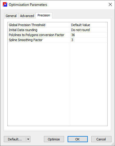
This enables fine-tuning of the polygons created to speed up optimization of complex shapes. It is recommended to leave the current settings in most situations, including for cabinetry.
The first parameter defines the number of segments per 360° during polyline to polygon conversion. The second parameter defines the smoothing rate for spline to polyline conversion during DXF import.