PolyBoard’s workshop document: cut list, plans and cost report
In this video we’ll show you how to print out and modify the cut list, plans and costings for your projects. All this information is included in the workshop document, with the option of adding extra dimensioned view angles of your cabinets.
Please note: sample output including the workshop document is available on the PolyBoard download page.
As well as the cut list, the part by part plans themselves include the locations of all machining, all sizes, edging positions and cut angles.
More details on the summary cost report and prices
The summary is the costing report that contains a detailed overview of the costs of the panel and bar materials used in the project, edging material, hardware, and tooling operations.
You can split the report into six sections.
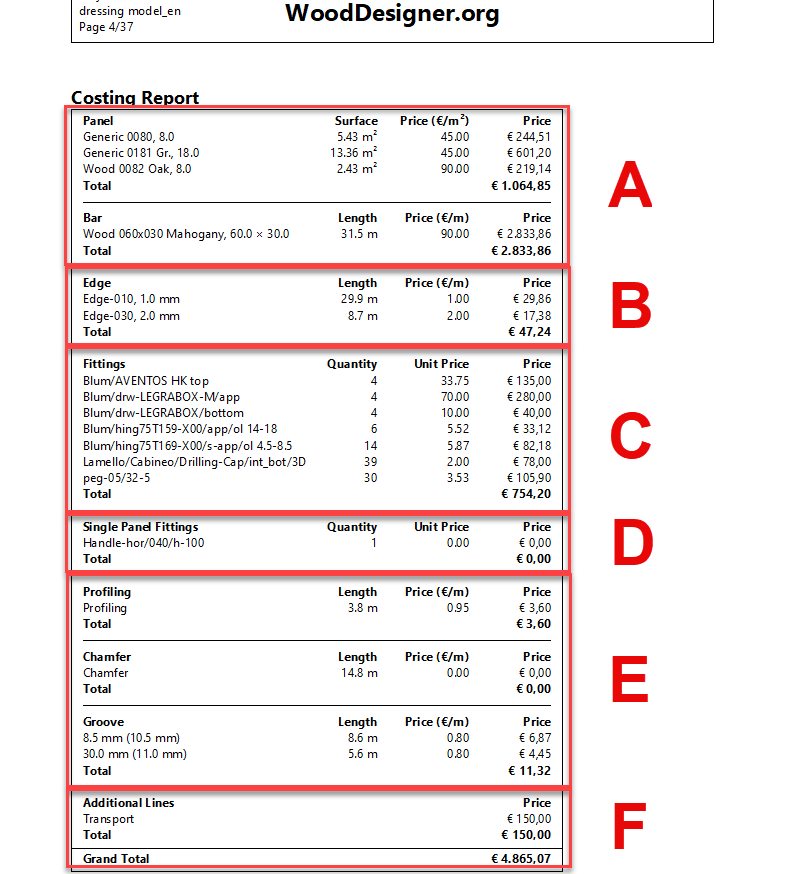
A: Panel and bar materials
PolyBoard calculates the used material for panels in surface per m² (other units can be chosen via the Tools menu > Units).
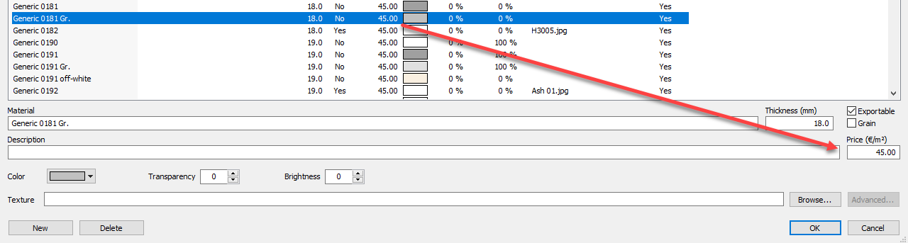
The price is set at the material level in the Panel materials library.
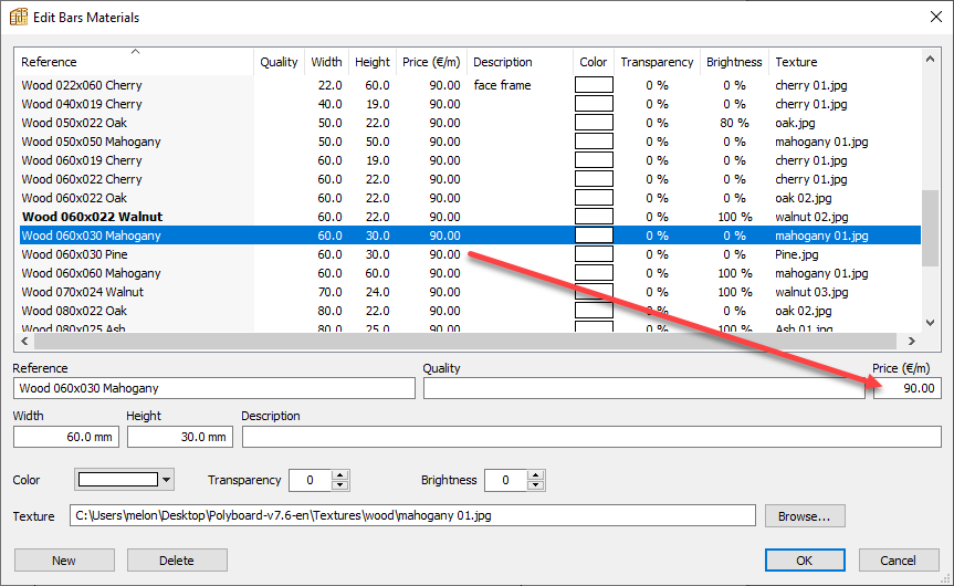
For bars, the price is per meter and set in the Bar materials library.
PolyBoard does not recognise panel sizes but only the material and the volume used.
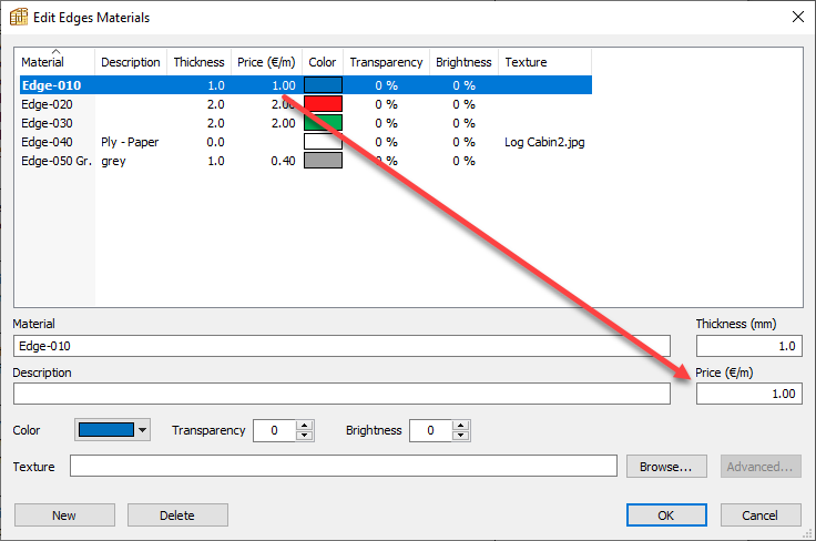
B: Edging
PolyBoard calculates the edge material in length per meter and the type of edging material.
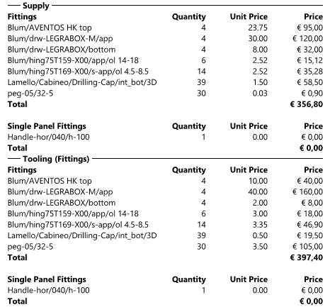
C: Fittings / Hardware
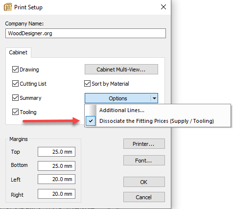
PolyBoard manages fittings via its Fittings library, where the price is set. The above report shows that the price per fitting is one unit price. This can be set in the options in the print setup. If the option is checked, the price will be viewed in both price elements, Supply and Tooling, where supply is the hardware and tooling is the cost for CNC machining.
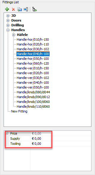
The price in the library is set as follows in the Fittings library:
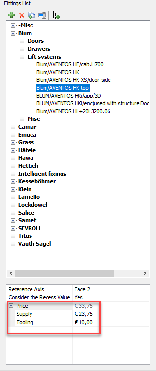
The total price is split into 2 different components:
- Supply
- Tooling
D: Single panel fittings
These are added in the report in the fittings section but as a separate sub-section. Single panel fittings represent accessory hardware, for example cabinet feet or handles.
The price is set in the Single panel fittings library, similar to the Fittings library:
The total price is split into 2 different components:
- Supply
- Tooling
E: Tooling prices (machining)
These prices can be set in the Tools menu > Tooling prices.
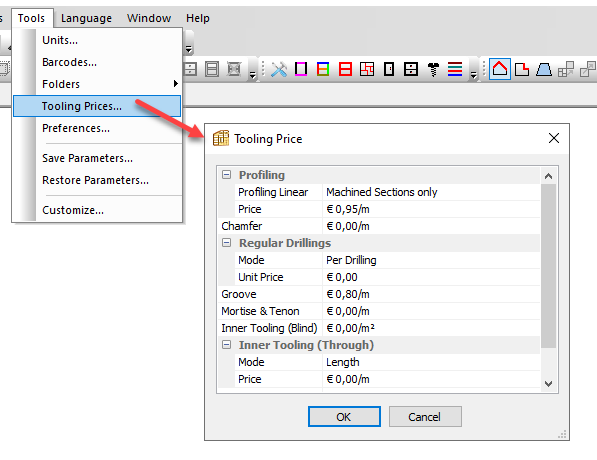
The prices will be shown in surface area or length depending on the type of tooling.
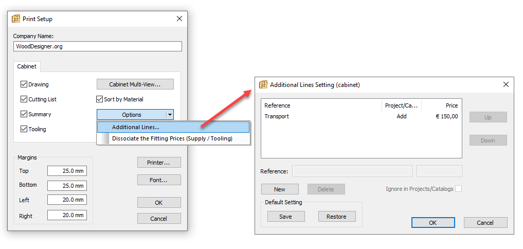
F: Additional lines
Extra costs can be added and saved in case of recurring costs on future projects.
In the above report, we added a transport cost. This can be done via the Print setup > Options > Additional lines.